FRENCH COMPOUND LOCOMOTIVES' HOMEPAGE

The KylChap; Patents #622.123 & #626.276 - 8/21/1926. Copies available from the I.N.P.I.

As usual, a larger version of each drawing can be seen by clicking the picture.

The Kylälä nozzle

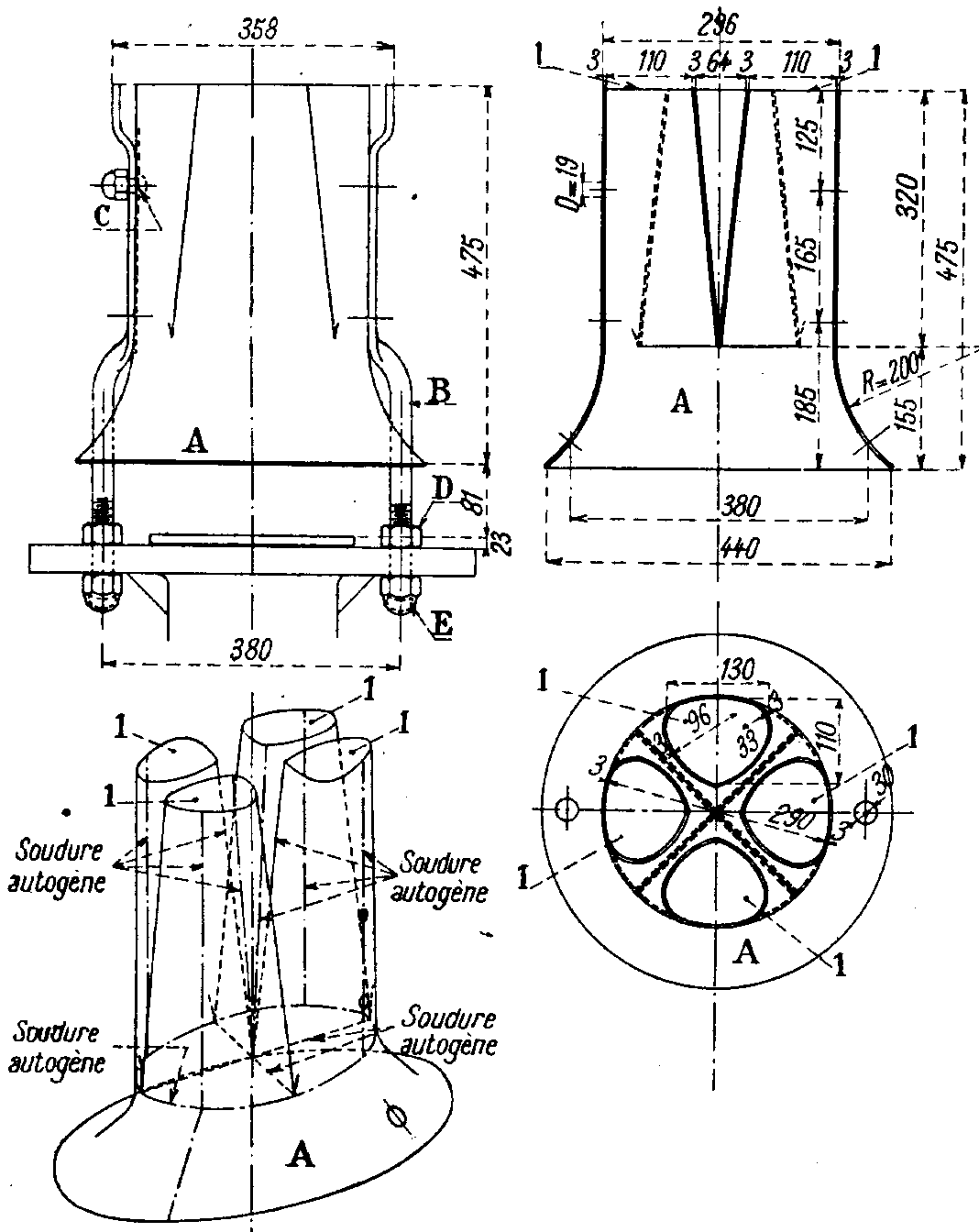
It's the "second stage" of the KylChap blasting (literal translation of French technical word for this part of a Marc Seguin's based design - I mean multiple smoketubes - of steam generator is exhaust, that's why I use it quite often and erroneously. Sorry.) Steam is "blown" in it by a first nozzle containing four triangular shaped blades . Drawings of it to come soon, but it can already be seen, not very clearly, in the drawing below.

Drawing: 39.4 K .gif file.

The full KylChap

Here you may immediately perceive one of the basic ideas of Chapelon about efficient blasting systems that is the necessity of multiples suction points and/or the necessity of a progressive, multi-points mixing of fluids (have a look at a drawing of a good injector), here we have 3 different suction points conveniently well vertically spaced in front of the tubes plate. The version shown here is the final one, called 1K/1C used in single, dual (called 1K/1C-1K/1C and not 2K/2C as often read) or triple (242 A 1) paralleled configurations according to the capacity and to the quantity of steam to be produced by the boiler. Relative positions and proportions of the various nozzles, independently of general dimensions, proven to be absolutely critical parameters to obtain an efficient KylChap, as are their perfect concentricity and alignment  (precision for "would be" KylChap modellers). Also note the four vital blades in the topmost Chapelon nozzle.

The triple KylChap of 242 A 1

The three basics paralleled KylChaps shown here being cut along three different vertical axis, most details are visible...

A very rarely shown drawing:

The "Super KylChap"

Fully annotated sketch by the hand of the master, unique opportunity to improve your technical french! But I can also help you a bit saying that Tuyère(s)=Ajutage(s)= nozzle(s)...

Mélange gazeux= gases mix.

Explanation of improvements awaited by Chapelon with this design is also on hand, currently under translation. Will come.

Briefly, the major difference, not very visible on this sketch is the addition of a second Kylälä nozzle above the Chapelon tuyère resulting in a fourth suction/mixing point.

Chapelon never tried to experiment with it, saying "... Difficulties to gain agreements to give solid form to highly valuables projects are already so hard, I don't want to fight again for such a minor idea."

  • 240.701 Chapelon 4 8 0, P.O. RailRoad (1932). - Dual Kylchap.

  • 241 D. 133 4 8 2 P.L.M. RailRoad (1942). - Dual P.-L.-M. RailRoad's blasting system (1 nozzle containing 4 blades of rectangular section in a cross arrangement), in French "à croisillon".

  • 241.004 Est (1937, see photo gallery). Est RailRoad's six jets (or lobes) said of clover type (and shape) blasting.

  • 3.500 P.-O.  RailRoad's PACIFIC (1932). Marcaut's clover type & shape (3 lobes) blasting.

  • 5.1203, Nord  RailRoad's DECAPOD (1939). Lemaître's blasting.

  • Loc,omotive 2687 P.-L.-M. (1909). - Nord's blasting.

  • Locomotive Crampton Nord (1859).- Double valve blasting.

  • Locomotive C 139 P.-L.-M. (1910). Echappement à double valve à noyau central.

  • Locomotive 01.021 de la Reichsbahn (1921). - Échappement circulaire fixe.

  • Locomotive 150.11.s du Pennsylvania (1923). - Échappement fixe à amorce de barrettes.

  • Locomotive 221 E. 6.8 du Pennsylvania (1912). -Échappement circulaire fixe.

  • Locomotive 242 de l'Union Pacific (1938). - Échappement fixe à quatre tuyères.

  • Locomotive 231. D. 21 P.-L.-M. (1922). - Échappement à trèfle P.-L.-M.

  • Locomotive 3.1290 Nord (1931). - Échappement Nord.


To be continued...


Hit Back
or
HOME


copyright 1997, 98, 99, 2000 by T. Stora. All rights reserved. Reproduction, translation, total or partial on any media absolutely forbidden without preliminary permission and agreement. Copyright 1997, 98, 99, 2000 by T. Stora